
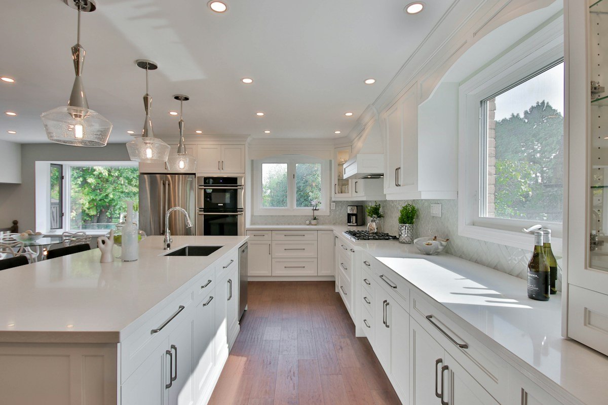
The quest for modern open-concept living has fundamentally reshaped the landscape of residential remodeling. Millions of mid-century ranches, suburban split-levels, and historic colonials were constructed around compartmentalized floor plans: isolating the home cook within a closed, claustrophobic kitchen partitioned off from the dining room and family living quarters. Today’s homeowners crave expansive, light-filled environments where cooking, casual dining, entertaining, and family life coalesce into a unified, flowing architectural space. Achieving this vision almost universally requires tearing down the central wall dividing the kitchen from the great room.
Yet behind the straightforward aesthetic desire for an open floor plan lies the most consequential structural intervention a residential building can endure: removing a load-bearing wall. Unlike non-structural partition walls that merely separate rooms and support their own drywall weight, a load-bearing wall is an integral component of the home’s primary gravity-resisting structural skeletal frame. It continuously supports the vertical loads of second-story bedroom floor joists, attic ceiling framing, roof rafters, and seasonal snow loads, funneling tens of thousands of pounds of downward force through its studs into the foundation beneath.
Far too many enthusiastic DIY homeowners and uncertified contractors treat wall removal as a casual demolition weekend armed with a sledgehammer. Striking down a load-bearing wall without engineered temporary shoring and permanent structural replacement triggers immediate catastrophic building settlement: sagging second-floor bedrooms, jammed doors, cracked drywall ceilings, fractured plumbing stacks, and potential catastrophic structural roof collapse. Removing a load-bearing wall is an exercise in structural engineering and carpentry physics that demands zero tolerance for error.
Executing an open-concept kitchen structural remodeling project safely demands strict adherence to certified engineering principles and municipal building codes. Synthesizing residential building code mandates from the International Code Council, structural steel engineering specifications from the American Institute of Steel Construction, timber design values curated by the American Wood Council, continuous load path directives from the Structural Engineers Association, and residential framing standards from the National Association of Home Builders, this comprehensive technical manual delivers an authoritative, step-by-step blueprint for engineering, shoring, sizing, and installing structural replacement beams when opening up a kitchen.
Structural Diagnostic Triage: Identifying Load-Bearing vs Partition Walls
Before making a single cut into drywall or ordering engineered beams, you must conclusively determine whether the targeted kitchen wall is load-bearing. While internet tutorials often claim that walls running parallel to ceiling joists are always non-load-bearing and walls running perpendicular are always load-bearing, real-world residential framing is far more complex and filled with subtle structural exceptions.
Investigative exploration begins in the unfinished attic or crawl space directly above the kitchen ceiling plane. Inspect the orientation of the ceiling joists relative to the wall in question. If ceiling joists or second-floor floor joists run perpendicular to the wall, resting their ends or overlapping their laps directly atop the double top plate of the wall, that wall is definitively load-bearing. The wall acts as an intermediate structural bearing support, cutting the joist span in half and carrying fifty percent of the joist gravity load.
Walls running parallel to joists can still be load-bearing under several common framing scenarios. If an attic features diagonal roof purlin struts or collar ties that angle down from roof rafters to land on a partition wall plate, that wall is actively carrying roof gravity and wind uplift loads down through the building. Furthermore, in two-story homes, an upper-level load-bearing wall carrying roof weight might sit directly above a main-floor wall running parallel to first-floor joists, transferring thousands of pounds of concentrated vertical force down through the assembly.
Tracing the continuous load path down into the basement or crawl space provides definitive structural confirmation. Go beneath the kitchen into the basement directly below the wall line. Do you see a heavy steel I-beam, a multi-ply solid timber girder, or a poured concrete foundation wall running directly beneath the kitchen wall above? If a structural girder supported by heavy steel teleposts (lally columns) aligns directly beneath the main-floor wall, that wall is the primary load-bearing spine of the house. Demolishing it without replacing its support will destabilize the entire central core of the residence.
Engineered roof truss systems present unique structural characteristics. In modern post-1970 homes built with engineered prefabricated metal-plate-connected wood roof trusses, the trusses are typically engineered to span clear distances of thirty to forty feet from exterior wall to exterior wall without requiring intermediate interior support. In pure clear-span truss homes, interior kitchen partition walls carry zero vertical roof loads. However, trusses must be inspected by a licensed professional engineer (PE) to verify that they were not engineered with intermediate interior bearing points or modified during previous renovations.
Gravity Load Tracing: Calculating Tributary Area and Concentrated Point Loads
Once a wall is identified as load-bearing, a licensed structural engineer must calculate the exact magnitude of gravitational force the wall supports. Sizing an engineered replacement beam cannot be based on guesswork or rules of thumb; it requires calculating the specific tributary area and adding up all dead loads, live loads, and environmental forces acting on the span.
Tributary width defines the physical strip of floor and ceiling framing whose weight is supported by the target beam. In simple terms, a beam supports half the distance to the next adjacent structural support on its left, plus half the distance to the next adjacent structural support on its right. For example, if a kitchen wall spans between a dining room with twelve-foot joists on one side and a kitchen with fourteen-foot joists on the other side, the tributary width supported by the wall is six feet (half of twelve) plus seven feet (half of fourteen), equaling a total tributary width of thirteen feet.
Uniform residential building code loading calculations combine dead loads and live loads. Under the International Residential Code (IRC Section R301), residential habitable floor areas mandate a minimum design live load of forty pounds per square foot (40 psf) to account for human occupants, heavy furniture, appliances, and movable items. Floor dead load: the permanent weight of the subfloor, hardwood flooring, framing timbers, and drywall ceiling: typically accounts for ten to fifteen pounds per square foot (10-15 psf). An unfinished attic requires ten to twenty psf, while roof loads incorporate local geographic snow load requirements ranging from twenty to over sixty pounds per square foot.
Converting uniform area loads into pounds per linear foot (plf) dictates beam strength. Multiplying the thirteen-foot tributary width by the total combined design load (for instance, 55 psf for a second floor plus 35 psf for a roof, totaling 90 psf) results in a uniform design load of 1,170 pounds per linear foot along the entire length of the wall! Over a sixteen-foot kitchen opening, the total downward force that was previously distributed across twelve wooden studs totals an astounding 18,720 pounds: over nine tons of gravitational pressure that must now be supported by a single replacement beam!
Concentrated point loads occur at both ends of the replacement beam. The beam collects this nine tons of distributed load and concentrates it into two massive point loads landing on the support posts at either end: each post must carry 9,360 pounds of downward force. This immense concentration of weight creates severe localized crushing stresses that must be safely transferred all the way down into solid concrete footings poured deep in the earth.
Lateral Shear Walls and Seismic/Wind Diaphragm Integrity
While homeowners and contractors instinctively focus on vertical gravity loads (preventing ceilings from collapsing downward), building structures are simultaneously subject to aggressive lateral environmental forces: horizontal wind pressures buffeting exterior siding and seismic ground acceleration waves during earthquakes. In residential wood-framed construction, certain central interior walls function not only as gravity-bearing elements, but also as designated structural shear walls.
A shear wall acts as a rigid vertical cantilever diaphragm that resists racking: the tendency of a rectangular house framing box to deform into a parallelogram when hit by lateral wind gusts. Shear walls are engineered with structural plywood or OSB sheathing nailed along tight four-to-six-inch perimeter schedules, anchored to the foundation with heavy-duty steel hold-downs (such as Simpson Strong-Tie HDU series tie-down brackets). If an engineer discovers that your central kitchen wall was designated as an interior shear wall in the original building plans, simply inserting a gravity beam is insufficient.
Compensating for the loss of an interior shear wall requires engineering alternative lateral resistance pathways. The structural engineer may specify upgrading the exterior kitchen walls with high-density structural sheathing and heavy hold-down anchors, or installing a prefabricated steel moment frame (such as a Simpson Strong-Wall or MiTek Hardy Frame) in the remaining stub wall returns. A moment frame provides rigid horizontal and rotational resistance within a narrow two-to-three-foot vertical column, allowing the kitchen span to remain wide open while preserving the building’s lateral wind and earthquake defenses.
Engineered Beam Selection: Steel I-Beams vs Laminated Veneer Lumber (LVL) vs Glulam
When selecting a structural beam to span the newly opened kitchen expanse, structural engineers evaluate bending strength, deflection limits, dimensional depth, weight, and installation clearances. The three primary structural beam materials specified in modern residential remodeling are engineered Laminated Veneer Lumber (LVL), Glue-Laminated timber (Glulam), and structural steel W-beams (I-beams).
Laminated Veneer Lumber (LVL) represents the most popular, cost-effective choice for residential remodeling contractors. Manufactured by ultrasonic testing and rotary-peeling wood veneers (typically Douglas fir or Southern yellow pine) coated with waterproof phenolic adhesives and cured under heat and pressure, LVL billets are dimensionally true and free of knots, splits, or warping. An LVL beam boasts an exceptional Modulus of Elasticity (E = 2.0E to 2.2E) and allowable bending stress (Fb) exceeding 2,800 psi. LVLs are manufactured in standard depths of 9-1/2″, 11-7/8″, 14″, 16″, and 18″ with a thickness of 1-3/4 inches per ply. Installers can carry individual plies into the home through standard doorways and laminate them together on-site using structural screws or through-bolts to create three-ply or four-ply composite beams.
Structural steel W-beams (wide-flange I-beams) provide the ultimate load-bearing capacity in ultra-compact depths. When an open kitchen span exceeds eighteen or twenty feet, or when low eight-foot ceilings prevent using a deep fourteen-inch wooden beam, structural steel is the only viable engineering solution. An eight-inch or ten-inch steel I-beam (such as a W8x24 or W10x30) can carry immense structural loads that would require a massive sixteen-inch-deep wood beam. However, steel beams are extraordinarily heavy: often weighing five hundred to eight hundred pounds: requiring specialized material lifts (Genie lifts) and ironworking rigging to maneuver into residential interiors.
Glue-Laminated timber (Glulam) offers architectural beauty when a dropped beam is intended to remain exposed as a rustic or modern design feature. Fabricated from individual layers of kiln-dried dimensional lumber bonded face-to-face with industrial adhesives, Glulams can be specified in architectural or premium appearance grades. Stained or clear-coated, an exposed Douglas fir Glulam beam provides rich timber warmth while delivering formidable structural stiffness across wide kitchen island spans.
Parallel Strand Lumber (PSL, commercially known as Parallam) provides extreme density for heavily loaded beams and heavy-duty structural posts. Formulated from long, narrow veneer strands oriented in parallel arrays and bonded under high pressure, PSL delivers phenomenal compression strength perpendicular to grain, making it an ideal choice for the heavy vertical columns supporting beam ends.
Flush Ceiling Beams vs Dropped Headers: Spatial Geometry and Joist Hanger Mechanics
A fundamental architectural decision during kitchen wall removal is deciding whether the replacement beam will sit dropped beneath the ceiling or installed completely flush within the ceiling plane. This decision dictates both the visual sightline between rooms and the physical complexity of the carpentry installation.
Dropped header beams sit completely beneath the ceiling joists. In this configuration, the existing ceiling joists remain uncut, resting their bottom edges directly on top of the new beam. The beam hangs down into the room by nine to fourteen inches, creating a framed visual archway or soffit separating the kitchen from the adjoining living room. Dropped beams are significantly simpler and less expensive to install because they do not require cutting existing ceiling joists or installing hundreds of structural metal joist hangers. Dropped beams can be wrapped in drywall, cased in finish carpentry trim, or fitted with recessed accent lighting.
Flush ceiling beams deliver the holy grail of modern minimalist architecture: an uninterrupted, continuous flat drywall ceiling plane running seamlessly from the kitchen across into the living room with zero downward protrusions. Achieving a flush ceiling requires recessing the entire structural beam up into the attic or floor joist cavity above the ceiling line. Every ceiling or floor joist on both sides of the wall must be temporarily shored, cut back precisely to make room for the new beam, and hung off the sides of the beam using heavy-duty galvanized structural joist hangers (such as Simpson Strong-Tie concealed-flange face-mount hangers).
Fastener engineering for flush joist hangers is unforgiving. Never use standard drywall screws, gold decking screws, or pneumatic finish nails to secure joist hangers; these brittle fasteners possess near-zero shear strength and will snap off under joist loading. Always use certified structural framing connector nails (such as 1-1/2″ or 2-1/2″ Simpson Strong-Drive SD screws or hot-dipped galvanized 10d common nails). Every single manufactured nail hole on the joist hanger face and side flanges must be completely filled with a specified structural fastener to achieve the engineer’s rated shear holding capacity.
Temporary Shoring Engineering: Double Shoring Walls and Hydraulic Jacking Protocols
The most hazardous phase of a load-bearing wall removal project occurs between the demolition of the old wall and the final installation of the new structural beam. During this vulnerable interval, the weight of the entire upper house must be supported by temporary shoring walls. If temporary shoring is improperly engineered or installed on a weak subfloor, the second story can drop inches in a split second, causing catastrophic structural damage.
Double temporary shoring walls are mandatory when joists on both sides of the wall rely on the central partition for support. Two temporary walls must be constructed parallel to the existing load-bearing wall: one on the kitchen side, and one on the living room side: positioned approximately two to three feet away from the existing wall to leave adequate working space for beam installation. Construct temporary walls using two-by-four or two-by-six framing studs spaced twelve or sixteen inches on center, sandwiched between a continuous top plate and bottom plate.
Distributing temporary shoring loads down through the floor system is critical. A temporary wall cannot simply sit on top of three-quarter-inch subfloor plywood mid-span between basement joists; the concentrated downward pressure will crush the subfloor and bend the floor joists beneath. The temporary bottom plate must either sit directly over an existing floor joist or be reinforced from below. Go into the basement or crawl space directly beneath the temporary shoring wall locations and install temporary basement shoring jacks (teleposts) or solid timber blocking tight against the basement subfloor, transferring temporary shoring loads directly down to the solid concrete basement slab.
Tightening and jacking temporary shoring requires meticulous, gradual calibration. Cut temporary shoring studs approximately one-quarter inch longer than the exact floor-to-ceiling height. Tap the studs into place with a small sledgehammer over wooden shims, or utilize twenty-ton hydraulic bottle jacks placed beneath a heavy timber header to lift the ceiling by a microscopic one-sixteenth to one-eighth of an inch: just enough to relieve gravitational pressure from the existing load-bearing wall studs. Never over-jack a ceiling; raising a ceiling by more than an eighth of an inch will crack plaster, warp second-story door frames, and fracture rigid copper plumbing lines.
Demolition Execution: Mechanical Rerouting and Hazardous Material Containment
Once temporary shoring walls are fully pressurized and verified, demolition of the load-bearing wall can proceed. However, residential partition walls are rarely empty; they act as primary mechanical highways housing electrical wiring circuits, plumbing supply and drain stacks, and HVAC forced-air ductwork that must be safely decommissioned and rerouted.
Electrical circuit discovery and safe isolation must precede all demolition. Kitchen walls frequently contain multiple twenty-amp small appliance branch circuits, lighting switches, and three-way traveler wiring. Use a non-contact voltage tester to verify all circuits are completely de-energized before cutting any cables. Electrical lines running through the wall must be pulled back into the attic or basement and re-routed through perimeter walls; hidden junction boxes buried inside finished drywall ceilings are strictly prohibited by the National Electrical Code (NEC).
Plumbing vent pipes and drain stacks running vertically through kitchen walls present complex rerouting challenges. If a second-floor bathroom drain stack (typically three-inch PVC or historic cast iron) or vent stack passes through the kitchen wall, it cannot be simply eliminated. It must be rerouted horizontally through floor joist cavities to a perimeter exterior wall, maintaining a strict downward slope of one-quarter inch per foot to ensure proper gravitational drainage without creating airlocks.
HVAC supply trunks and return air chases running through the wall cavity must be relocated. In two-story homes, the central kitchen wall often serves as the primary return air chase for the second floor. Work with a licensed HVAC contractor to reconfigure ductwork, routing new insulated flexible or sheet metal ducts through closets or creating an architectural drywall chase in an unobtrusive room corner.
Systematic stud removal follows mechanical clearing. Cut through the vertical framing studs at mid-height using a reciprocating saw equipped with a heavy-duty metal-cutting carbide blade to sever hidden nails. Pull the cut stud halves free from the top and bottom plates. Finally, pry the bottom sole plate off the subfloor and unfasten the double top plate from the joists, leaving a completely open, clean framing pocket ready for the new structural beam.
Structural Bearing Points: Jack Stud Multiples, King Studs, and Bearing Lengths
A structural beam is only as strong as the vertical columns supporting its ends. All the gravitational weight collected across an eighteen-foot kitchen opening must transfer down into the support posts at either end. Calculating the number of jack studs and verifying allowable compressive bearing stress prevents post crushing.
Jack studs (also known as trimmer studs) are the vertical framing timbers that sit directly beneath the bottom face of the beam, physically supporting its downward weight. King studs are full-height studs running alongside the beam from floor to ceiling, nailed rigidly to the jack studs and beam ends to provide lateral stability and prevent twisting. Under the International Residential Code (IRC Table R602.7(1)), the required number of jack studs is determined strictly by the beam span and tributary width. While a small five-foot door header requires only a single jack stud, a twelve-to-sixteen-foot kitchen beam carrying floor and roof loads routinely mandates two, three, or four continuous jack studs (or a solid 6×6 PSL post) at each end.
Bearing length standards are governed by wood crushing physics under ASTM D143. Wood grain is significantly weaker in compression perpendicular to grain than parallel to grain: if a heavy steel or wooden beam rests on only an inch of wood, the concentrated weight will crush the wood fibers like a sponge, causing the beam to settle. IRC building codes mandate that beams have a minimum bearing length of one-and-one-half inches on wood framing and a minimum of three inches on masonry or concrete. For large residential spans exceeding fourteen feet, structural engineers typically require a minimum bearing length of three to four-and-a-half inches: matching the full thickness of two or three laminated jack studs.
Fastener fastening schedules for composite post assemblies ensure unified structural action. When assembling multiple two-by-fours or two-by-sixes into a composite support column, the studs must be mechanically laminated together using three 10d (three-inch) common nails or structural screws every twelve inches along the entire height of the post. This prevents individual studs from buckling laterally under extreme vertical axial compression.
Continuous Load Paths to Foundation: Teleposts, Footing Pads, and Basement Pier Reinforcement
The single most dangerous blind spot in DIY wall removal projects is failing to follow the load path below the main floor. Homeowners successfully install a massive steel beam and heavy jack posts on the main floor, completely forgetting that the thousands of pounds of concentrated weight resting on those posts are pushing straight down into the floor joists beneath them. In the building code, gravity loads must maintain an unbroken, continuous load path all the way down into the solid earth.
Inspecting the subfloor framing directly beneath both beam support posts is mandatory. If a support post lands directly on a floor joist mid-span in the basement, that floor joist will quickly buckle, sag, or shear under the concentrated nine-thousand-pound point load. Solid timber blocking must be packed tightly between the basement floor joists directly beneath the post footprint, transferring the load solidly down to the structural basement framing below.
Adding dedicated steel teleposts (lally columns) in the basement directly aligns with the point load above. Beneath each main-floor post, a heavy-duty three-and-a-half-inch steel column filled with concrete must be installed in the basement or crawl space, clamped securely to the underside of the floor framing. This column carries the concentrated post load straight down to the basement floor.
Basement concrete slab limitations dictate whether new footing pads must be poured. Standard residential basement concrete slabs are barely three to four inches thick and are designed to support light walking traffic, not concentrated multi-ton point loads. Placing a heavy telepost directly on a thin basement slab will punch a hole straight through the concrete like a cookie cutter. Structural engineers require saw-cutting a two-foot-by-two-foot square out of the existing basement slab, excavating twelve inches of soil, and pouring a reinforced concrete footing pad (typically 24″ x 24″ x 12″ deep reinforced with a grid of four number-four rebar bars placed three inches above the bottom) using high-strength 3,500 to 4,000 PSI concrete to distribute the post load safely into undisturbed subsoil.
Fireblocking and acoustic dampening must be incorporated before closing open ceiling cavities. Removing an interior wall breaches the fire-resistive membrane separating living compartments. Building codes mandate installing solid two-inch dimensional lumber fireblocking or certified mineral wool insulation at all ceiling intersections to prevent the vertical spread of flame, smoke, and toxic gases inside concealed joist cavities. Furthermore, wrapping flush steel beams or multi-ply LVLs in dense rockwool battens dampens structural sound transmission between kitchen dining areas and second-floor bedrooms.
Permitting, PE Engineering Stamps, and Municipal Inspection Sequences
Removing a load-bearing wall is never a cosmetic DIY project that can be executed without municipal permits. Building departments classify wall removal as major structural alteration that directly impacts building life safety. Proceeding without permits invalidates homeowners insurance coverage, creates severe legal liability if an accident occurs, and complicates future real estate sales when buyers demand proof of permitted structural work.
Working with a licensed Professional Engineer (PE) or licensed residential architect represents the mandatory first step. The engineer conducts on-site measurements, calculates tributary loads, designs temporary shoring plans, specifies exact beam dimensions and fastener schedules, and generates an official structural engineering drawing stamped with their professional state PE seal. This stamped engineering document is submitted to your local municipal building department along with your permit application.
Municipal inspection choreography follows a strict sequential timeline. After permits are issued, you must complete the temporary shoring, remove the wall, install the beam, hangers, posts, and foundation columns. Before covering a single piece of framing with drywall or insulation, you must schedule a rough framing inspection. The municipal building inspector inspects beam model numbers, verifies the PE stamp specifications, checks joist hanger nail schedules, confirms bearing lengths, and inspects basement footings. Only after the inspector signs off on the framing permit can drywall installation and finish carpentry proceed.
Structural Beam Systems and Load Capacities Comparison
Selecting the optimal structural beam system requires balancing span capability, vertical ceiling clearance, material weight, lifting logistics, and fabrication budget. Sprawling twenty-foot openings with eight-foot ceilings demand high-strength structural steel, whereas fourteen-foot openings in rooms with nine-foot ceilings are ideal for multi-ply Laminated Veneer Lumber.
Evaluating beam systems against certified engineering properties ensures that your investment achieves permanent structural stiffness, zero ceiling sag, and flawless open-concept architectural elegance.
The comparative matrix below evaluates the structural material composition, span capability, vertical profile depth, weight per foot, installation complexity, and ideal application zones for the six primary structural beam systems specified in residential remodeling today.
| Structural Beam System | Maximum Residential Span | Profile Depth Efficiency | Weight per Linear Foot | Installation Logistics | Ideal Application Zone |
|---|---|---|---|---|---|
| Multi-Ply LVL (3-Ply to 4-Ply) | 16 – 20 Feet | 11-7/8″ to 14″ Deep | 15 – 22 lbs / ft (assembled) | Moderate (Carry 1 ply at a time) | Standard kitchen wall removals, dropped headers |
| Structural Steel W-Beam (I-Beam) | 22 – 30+ Feet | 8″ to 10″ Ultra-Compact | 24 – 35 lbs / ft (Very Heavy) | Advanced (Requires Genie material lift) | Long clear spans, low ceilings, flush installations |
| Architectural Glulam Timber | 18 – 24 Feet | 12″ to 16″ Deep | 18 – 26 lbs / ft | Advanced (Single solid heavy beam) | Exposed decorative timber beams, rustic open kitchens |
| Parallel Strand Lumber (Parallam PSL) | 18 – 22 Feet | 11-7/8″ to 14″ Deep | 20 – 28 lbs / ft | Advanced (High material density) | Heavy point loads, supporting posts, high shear spans |
| Flitch Plate Beam (Wood + Steel Core) | 14 – 18 Feet | 9-1/2″ to 11-7/8″ Slim | 25 – 32 lbs / ft | Intermediate (Thru-bolted sandwich) | Moderate spans requiring timber nailing faces |
| Solid Sawn Timber (Built-up 2x10s) | Under 10 Feet | 9-1/4″ Deep (Subject to sag) | 10 – 14 lbs / ft | Simple (Manual framing carpentry) | Short openings (window/door pass-throughs only) |
Reviewing these structural parameters confirms why engineered LVLs and structural steel dominate residential open-concept remodeling. By matching your beam selection to clear span physics and providing unbroken load paths down to solid foundations, your home renovation achieves enduring architectural stability and breathtaking spatial grandeur.
Frequently Asked Questions About Removing Load-Bearing Walls
How can I tell for sure if a kitchen wall is load-bearing?
Inspect the joists directly above the wall in the attic or ceiling. If ceiling joists or second-floor floor joists run perpendicular to the wall and rest on top of it, the wall is load-bearing. Check the basement directly below the wall line: if a steel girder, foundation wall, or telepost row runs directly underneath, the wall above is carrying the main structural load of the home.
Can any load-bearing wall be removed in a residential house?
Yes, virtually any load-bearing wall can be safely removed, provided that its structural load is redirected to an engineered replacement beam (such as an LVL or steel I-beam) supported by adequate posts and foundations. However, the cost and engineering complexity increase significantly if the wall contains major plumbing stacks, electrical panels, or HVAC ductwork.
What is the difference between a flush beam and a dropped beam?
A dropped beam sits directly beneath the ceiling joists, protruding down into the room by nine to fourteen inches and creating a visible soffit or archway. A flush beam is recessed completely up into the ceiling joist space, with all joists hung off its sides using metal joist hangers, creating an unbroken, flat ceiling plane running seamlessly between rooms.
Do I need a structural engineer to remove a load-bearing wall?
Yes, municipal building codes require calculations and a stamped drawing from a licensed Professional Engineer (PE) or architect before issuing building permits for load-bearing wall removal. The engineer calculates tributary roof and floor loads, specifies exact beam dimensions, details temporary shoring, and designs basement footing reinforcement.
How much does it cost to remove a load-bearing wall in a kitchen?
Total project costs typically range between ,500 and ,000 for a standard twelve-to-sixteen-foot opening using an engineered LVL beam, including engineering fees, permits, temporary shoring, and beam installation. If structural steel is required, or if plumbing, HVAC, and electrical lines must be rerouted through perimeter walls, costs can range from ,000 to ,000.
What happens if you remove a load-bearing wall without temporary shoring?
Removing a load-bearing wall without temporary shoring walls causes immediate structural settlement. Second-floor bedroom floors will sag, ceiling drywall and plaster will crack extensively, second-story doors and windows will jam shut, roof rafters will deflect, and plumbing pipes can shear, potentially culminating in catastrophic structural collapse.
What are jack studs and why are multiple studs required?
Jack studs (trimmer studs) are vertical framing timbers that sit directly beneath the ends of the beam to support its downward weight. Because long beams concentrate thousands of pounds into small point loads, a single stud will crush under the compression stress. Structural codes typically require two, three, or four laminated jack studs beneath each beam end.
Does the foundation in the basement need reinforcement when removing a wall?
In most cases, yes. A load-bearing wall previously distributed its weight across ten to fifteen studs. When replaced with a beam, that entire load is concentrated into two small point posts. If these posts sit on a thin basement concrete slab, they can punch through the floor. Pouring a 24x24x12-inch reinforced concrete footing pad beneath the basement teleposts is standard engineering protocol.
Can I use solid wood 2x10s or 2x12s instead of an engineered LVL beam?
Traditional dimensional lumber (like Douglas fir 2x10s) is generally inadequate for spans exceeding eight to ten feet under modern load codes. Sawn lumber contains natural knots and grain slope that reduce strength and promote long-term creep sag. Engineered LVLs and steel provide double the stiffness and remain dimensionally true without sagging over decades.
How long does the physical wall removal and beam installation process take?
The physical structural carpentry: building temporary shoring walls, removing the existing wall, installing the engineered beam and support columns, and attaching joist hangers: typically takes two to four days for an experienced framing crew. Mechanical rerouting (electrical, plumbing, HVAC) and drywall finishing add another one to two weeks.
Architectural Verdict and Open-Concept Living Transformation
Removing a load-bearing kitchen wall is the single most transformative structural investment you can make in an older residential home. By dismantling obsolete physical barriers, you unlock natural sightlines, flood interior rooms with bilateral daylight, and create a warm, collaborative culinary environment that serves as the vibrant social heartbeat of family life.
Executing this transformation with safety and architectural dignity requires respecting the immutable laws of structural physics: identify bearing paths with diagnostic precision, calculate tributary loads with licensed engineering rigor, build rigid double shoring walls to secure the upper stories, specify dimensionally stable LVL or steel beams, and anchor support columns to reinforced foundation pads deep in the earth.
When engineered with uncompromising craftsmanship and permitted according to code, your open-concept kitchen remodel does not merely create a modern aesthetic; it permanently enhances the structural integrity and market value of your residence: building a luminous, enduring architectural sanctuary where cherished memories are shared for generations to come.